![]() Great Western Main Line ATP Pilot Scheme
Great Western Main Line ATP Pilot Scheme
|
During 1989 and 1990, 89 HST power cars were fitted with the Belgian ACEC TBL Automatic Train Protection (ATP) system at Landore depot, Swansea. Initially running out of Bristol St Phillips Marsh (SPM) depot the HST trials on GWML eventually settled into a pattern of running between Swindon and Bristol Parkway (Stoke Gifford) on the Badminton Line. This was the first part of the route to be fully fitted with the ATP lineside equipment. The power cars were equipped with an antenna which received information from the track-mounted beacons and loops and a tachometer to record distance travelled. The cab equipment included a driver's display to convey information to the driver and a data entry unit to allow certain parameters to be entered into the on-board computer as required. The computer was contained in a large enclosure and was mounted in the van end of each power car and was known as the Vehicle On Board Controller (VOBC). Track equipment was original only fitted between Swindon and Bristol Parkway but later it was extended all the way to Paddington (on the fast lines only from Reading), although Paddington station wasn't fitted until a lot later. In the other direction it was fitted past Wootton Bassett junction to Dr Days at Bristol. It was also fitted on the Berks and Hants line from Reading to just short of Newbury but this was only fitted in parts therefore allowing further trials of the system as it ran over track with and without ATP towards Newbury. This stretch also included a couple of level crossings at Thatcham and Midgham the protection of which was also being evaluated. The track equipment consisted of an aerial (or beacon) located in the four foot at each signal plus in-fill beacons between signals in certain locations to enable information for the train to be updated more rapidly if necessary. These were supplemented with long loops of cable in rear of certain signals e.g. at junctions, to allow even earlier updates of signal aspect changes. These cable loops could be up to 1000m in length and the principle was introduced in order to keep traffic flowing. The HST test train usually started from Swindon but would have come down empty from Paddington - three round trips between Swindon and Bristol Parkway Yard then we would bale out back at Swindon and the HST would return ECS to London for an evening departure from Paddington. Initially we were riding shotgun during the extensive driver training running but later we were dictating the test running to evaluate the system and to trial modifications etc. As the on-track equipment fitment progressed, the test trains ran over different parts of the route. Eventually Paddington station was fitted and this included buffer-stop protection. Trials for this protection system were carried out at Newbury Racecourse station where we could set up different scenarios without interfering with the main line and there were no real buffers stops - just an indicator on the platform. By 1998, as a result of the original Class 332 Heathrow Express units being fitted with ATP from new, the relief lines were finally equipped throughout with the system. The signals inside the Heathrow tunnels have 'double beacons' as a safeguard against failure. I remember stopping at the Posthouse Hotel on the outskirts of Swindon and later we combined the GW and Chiltern jobs and we stayed at Aylesbury (in the company of other colleagues for a change) and drove to and from Swindon each day. Click on the image for a bigger picture - all pictures are the author's unless otherwise credited |
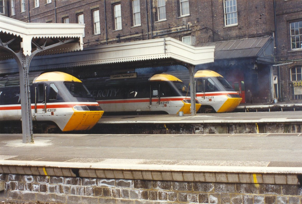 |
Three ATP-fitted HST power cars at Paddington in 1992 |
|
The ACEC system consisted of a Vehicle On Board Controller (VOBC) mounted in a large metre-square box in the van-end of the power car-see below. An antenna was fixed to the underside of the leading bogie which received signals from beacons positioned at each signal. An axle-mounted tachometer recorded distance travelled. Data was also entered by the driver about the train type and its braking performance, although most of the data for a standard HST was already programmed in. |
|
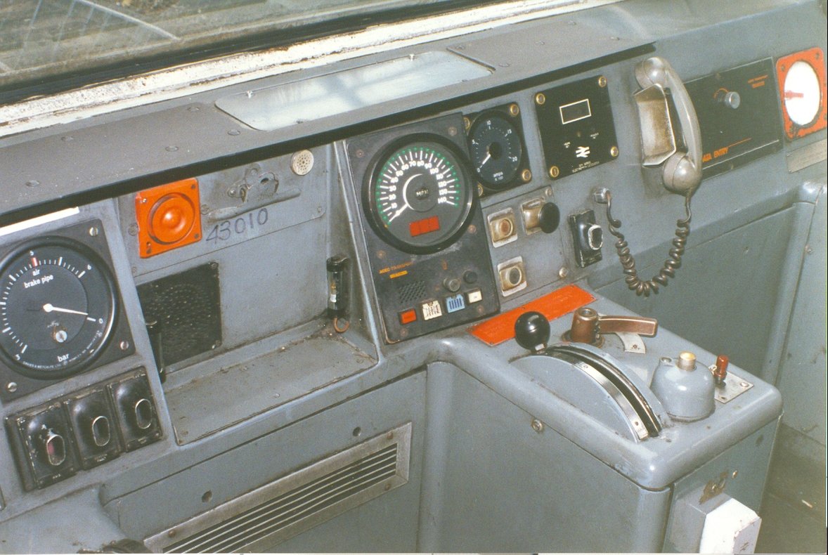 |
Inside the cab the standard
speedometer was replaced with an ATP speedo and a data entry unit was fitted - the keypad was
behind the black panel visible on the
right hand side next to the telephone handset. Author's collection |
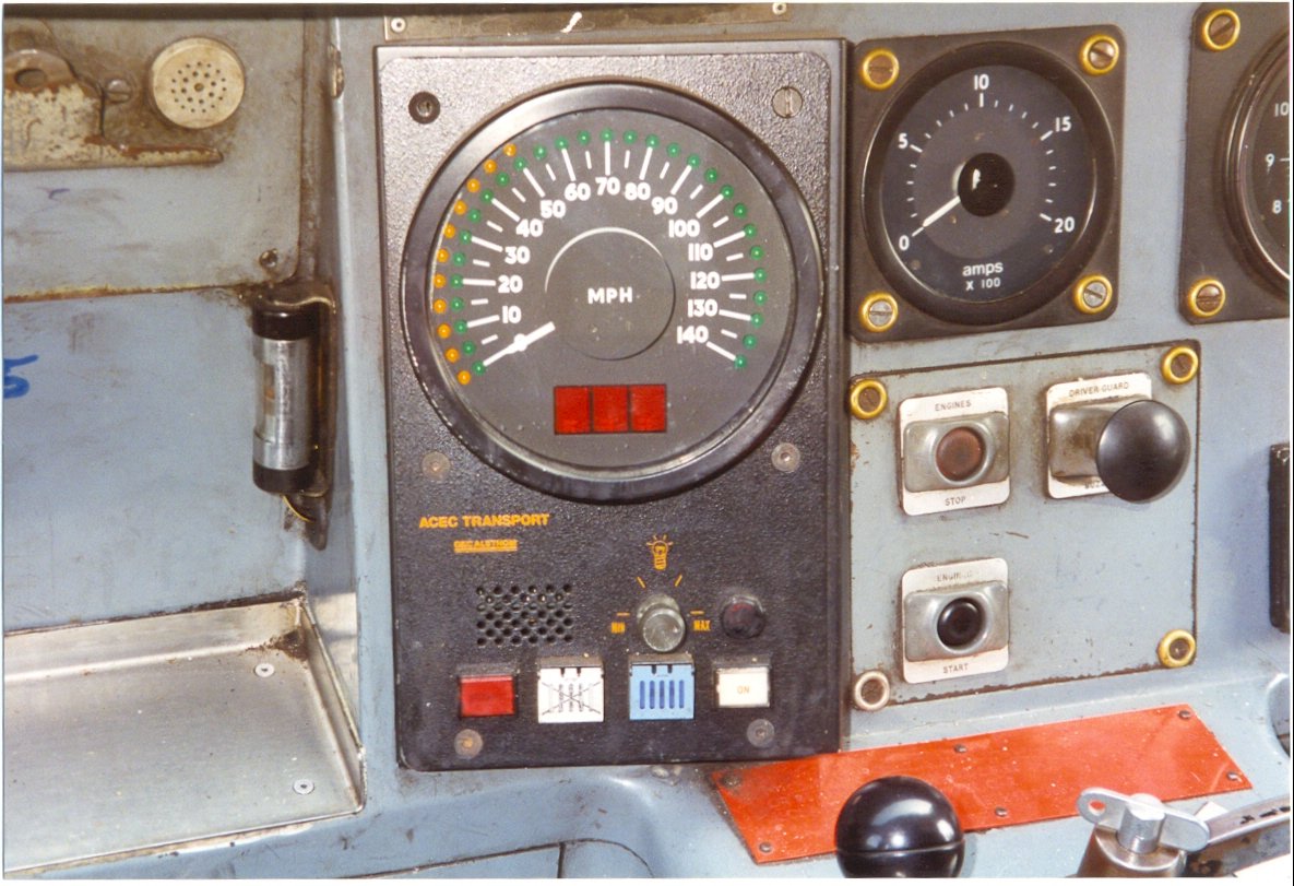 |
A close-up of the speedometer reveals the LEDs around the circumference and a number of additional displays for the driver's information together with four interactive buttons |
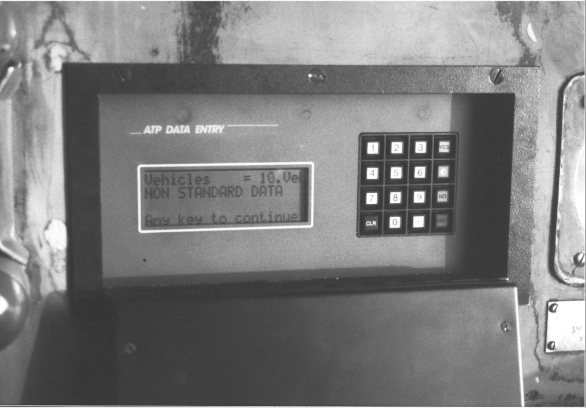 |
The driver's PIN number together with 'Standard' data was entered by the driver via a keypad beneath a drop down door. Any other data related to any non-standard performance issues or train make-up could also be entered here as required. |
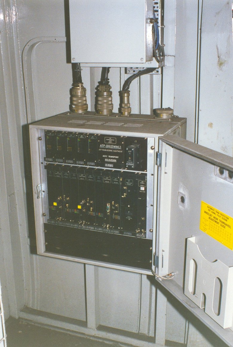 |
The VOBC
was mounted in the van end and had inputs from the driver's display, the
data entry unit, the axle-mounted tachometer and the antenna - which was
mounted on the rear of the leading bogie next to the AWS receiver. Author's collection |
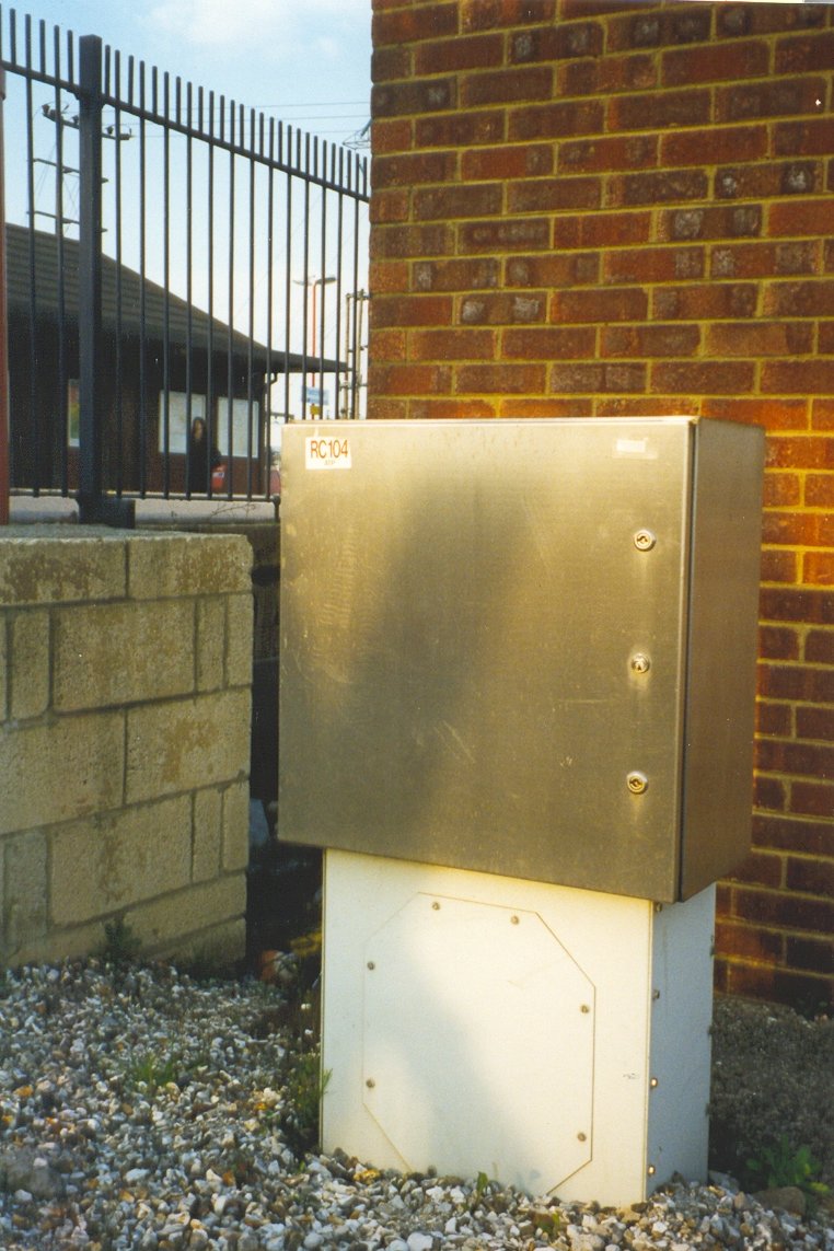 |
The trackside ATP electronics and interface
with the conventional signalling for the lineside equipment were mounted in
new cabinets with an attractive stainless steel finish. This equipment
processed the messages which were transmitted to the trains via the
track-mounted beacons and loops. An EPROM with information related to the
location of the signal, the line speed, the distance to next signal etc
would be fitted within. The signal aspect would be incorporated into this
data. This EPROM could be replaced with another when introducing a temporary
or emergency speed restriction as required (TSR or ESR) Author's collection |