E R Morten
|
The tests which form the subject of this Bulletin were carried out on a B.T.H/Paxman Type 1 800 H.P. B-B diesel-electric locomotive, one of the early casualties of the standardisation of diesel types after the vagaries of the Modernisation Plan. Three designs of Type 1 800/1000 B.H.P. locomotives were ordered by the British Transport Commission under the 1955 Pilot Scheme, and they were primarily intended for freight-transfer duties. Carriage heating boilers were not therefore installed, although through steam pipes were fitted to enable them to work in tandem with locomotives fitted with carriage heating equipment. The first design to emerge was the English Electric Type 1 1000 H.P. B-B diesel-electric locomotive which was the subject of Bulletin No.11. The B.T.H/Paxman 800 H.P. locomotive was the second design to be put into service. Although both of these locomotives were of comparatively small power, and intended for similar duties, each incorporates distinctive design features. Referring briefly to the English Electric 1000 H.P. locomotive described in Bulletin No.11, the power was supplied in this case by an 8 cylinder Vee engine with rated output of 1000 H. P. at 850 r. p. m. The main generator excitation was supplied by the auxiliary generator and controlled by a torque regulator in the main generator field circuit. The four traction motors were connected in series – parallel and had three stages of field weakening. By comparison the 800 H.P. B.T.H/Paxman locomotive employed a 16 cylinder engine with cylinders arranged in Vee formation, and developing 800 B.H.P. at 1250 r.p.m. The electrical transmission system followed the usual B.T.H practice of providing a separate exciter for the main generator instead of excitation being taken from the auxiliary generator. The four traction motors were connected permanently in parallel and only one stage of field weakening was employed. The tests described in the Bulletin were carried out to determine the performance and related fuel consumption of an 800H.P. B.T.H/Paxman locomotive over its working range, and at the same time to provide data for calculating train schedules. A further object was to obtain sufficient data to demonstrate the distinctive features of the electrical transmission system. An extensive programme of tests with the Mobile Test Plant was accordingly planned and carried out by the Locomotive Testing Section of the Chief Mechanical and Electrical Engineer's Department, London Midland Region. The work was conducted on behalf of the Locomotive Testing Joint Sub-Committee. THE LOCOMOTIVE The test locomotive was one of the batch of ten supplied in 1957-8 by the British Thomson-Houston Co., the main contractor. The engines were provided by Davey Paxman & Co. Ltd., the electrical equipment by B. T. H., the bogies and superstructure by the Clayton Equipment Co. Ltd., and underframes by the Yorkshire Engine Co. Ltd., who also undertook the locomotive erection. Locomotive No: D8208,selected for the tests, had run 5900 miles before road testing commenced, and covered a further mileage of 2530 during the course of the tests. Here are a few pictures of the tests. |
Pictures are BR official except where credited
|
|
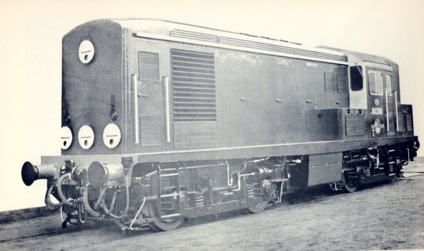
The builder's photograph of D8200 |
|
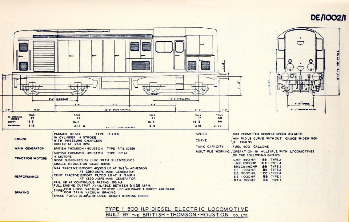
BR diagram entry for D8200 class |
|
|
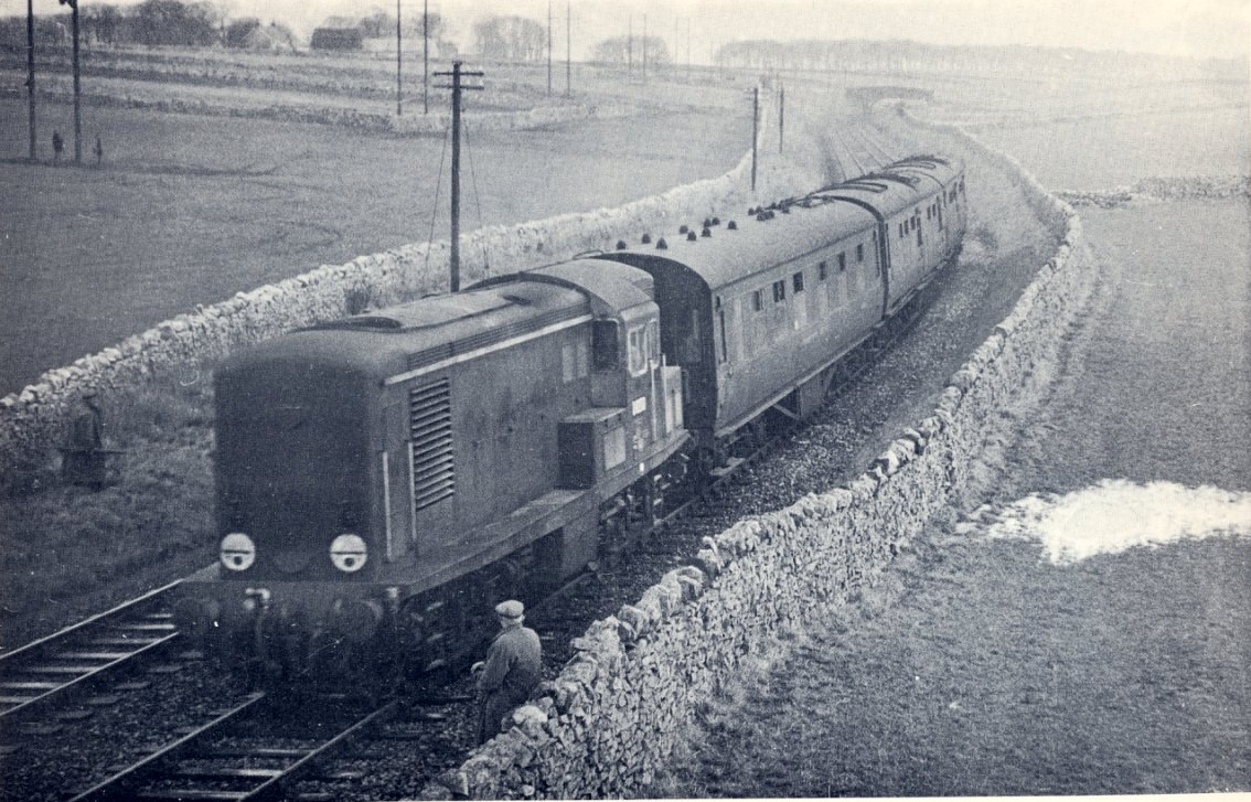
The test train is pictured on
the Ashbourne - Buxton line with the dynamometer car and a couple of MTUs. E R Morten |
|
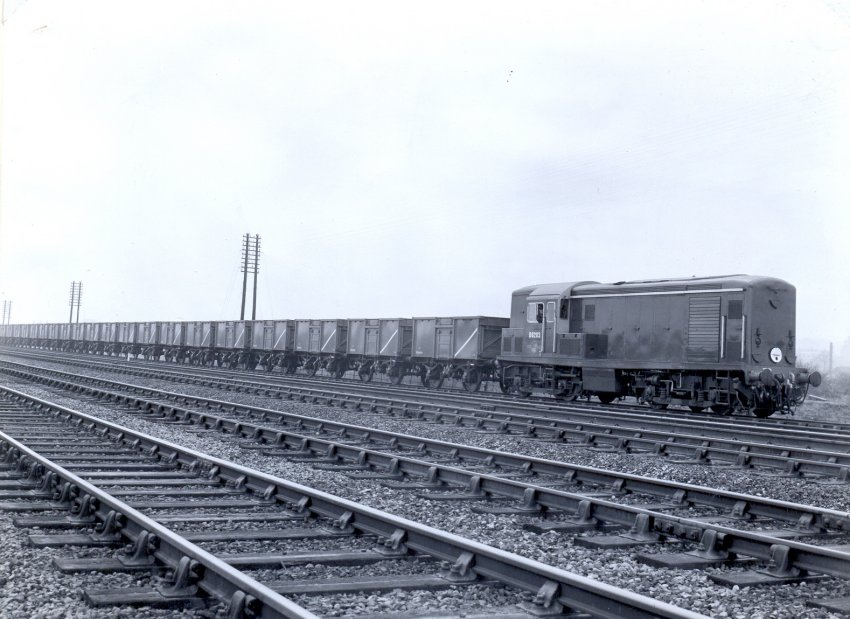
Another of the class on a mineral wagon test train near Ilkeston |