The subject of this Bulletin was the well known Southern Region "Merchant Navy" Class 4-6-2 steam locomotive, as modified with separate valve gear to each of its three cylinders. The Bulletin placed on record the results of tests which were undertaken to establish the principal relations involved in the conversion of heat into useful mechanical work and the principal factors involved in this conversion that were of especial value in design problems.
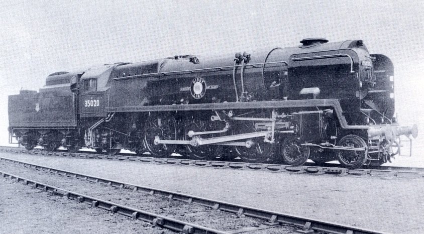
The locomotive chosen for the tests was 35020 'Bibby Line', one of the "Merchant Navy" class which had been modified at Eastleigh Works shortly prior to the tests. This class was introduced on the Southern Railway in 1941, and 30 locomotives in all were built at Eastleigh in three batches, the last of which was constructed in 1949. Although the locomotives in their original form, followed the normal design tendencies for a Pacific type with three cylinders and a wide firebox, there were several features which were not usually employed in British locomotive practice, among which were:
|
A three-throw crank shaft, chain driven from the driving axle, which operated valve gear for each of the three cylinders. Each gear was connected to its respective piston valve through a rocking lever arrangement having a 3:8 ratio. | |
|
An oil-bath enclosing :the three sets of special valve gear and the inside motion. This was intended to give continuous lubrication to the working parts. | |
|
A smokebox of irregular shape, as opposed to the more usual cylinder. | |
|
Special casing over the whole of the upper part of the locomotive. |
Whilst the locomotives had given
sterling service and demonstrated their ability to run to time, with an ample
margin of power, due to their excellent steaming capabilities and free running
characteristics, some of the features enumerated above have proved troublesome,
with the result that the locomotives were not entirely satisfactory from the
point of view of availability. In addition, their consumption of coal, oil and
water was high in comparison with other modern locomotives.
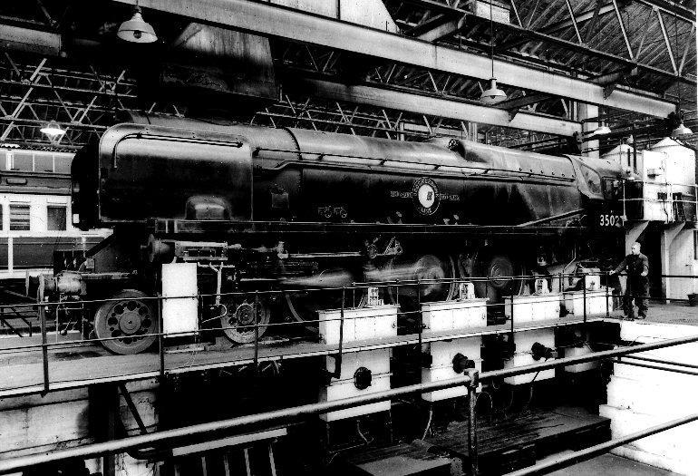
To overcome these difficulties, modifications are being carried out to the whole
class and the locomotive tested No:35020 was the second to be dealt with.
Boiler
The boiler itself was unaltered but the air-smoothed casing, which formerly enveloped it and the smokebox, was dispensed with and replaced by orthodox boiler clothing plates mounted on crinolines. The fibre-glass mattresses were retained. To bring the locomotives up to the latest standards, in the interests of good combustion on long runs, and rapid turn-round, they were fitted with a rocking grate with 12 rocking sections, 6 on each side of the centre line. Each rocking section carried 15 renewable finger type firebar units giving a 37.3% air space.
A new ashpan was fitted having four bottom doors for self emptying. This retained a feature of the previous ashpan which was its division into three parts, consisting of a central section between the frames, and two outer sections. The former now had two hoppers, each with bottom doors, the rear leg passing through the reins of the trailing truck. Two damper doors were provided in the central section, the forward door being hinged from the front leg and the trailing door from the rear leg. The outer sections of the ashpan had one hopper each, in line with the front leg of the central section. Two damper doors were provided on each of the outer sections of the ashpan so that, in all, there were three damper doors facing forwards and three facing rearwards. .The damper doors were operated in two groups by screw control on the footplate, each group comprising doors facing forwards and doors facing rearwards, respectively.
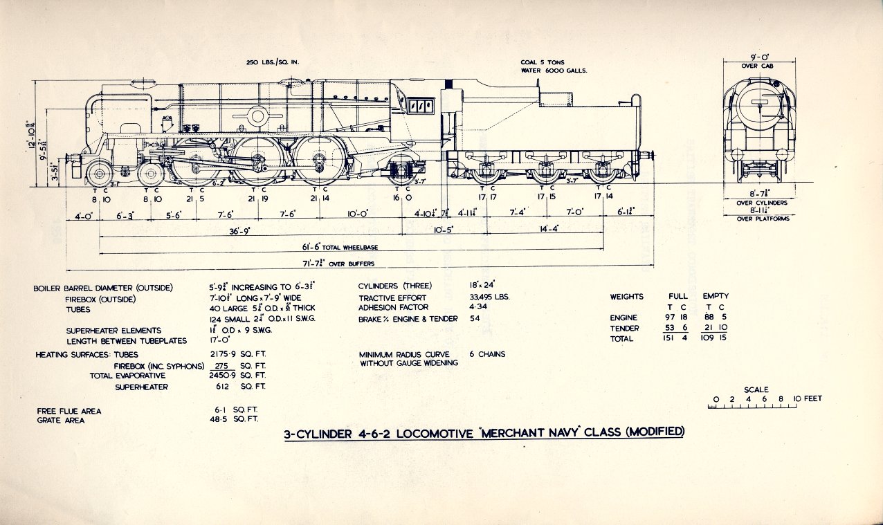
The boiler was of normal design and was very similar to that used subsequently in the B.R. Standard Class 8 Express Passenger locomotive (Duke of Gloucester), except that it had a steel firebox and two thermic syphons. The grate area was 48.5 sq. ft., the evaporative heating surface 2450.9 sq.ft., and the superheater heating surface 612 sq.ft. The ratio of evaporative to superheater surface was 4 to 1.
Smokebox and Draughting Arrangements.
A new smokebox of the orthodox cylindrical shape was provided which rested on a saddle, part of which was formed by the upper portion of a new inside cylinder and the remainder by a new fabricated saddle stretcher. The smokebox was surmounted by a cast iron chimney having a choke diameter of 1ft 111/2" and the taper of the diverging portion is 1 in 4.73. The chimney was fitted with a petticoat and ejector exhaust ring. The multiple jet blast pipe was retained having five circular converging nozzles of 2.5/8" diameter. No self-cleaning plates were fitted.
Cylinders
The three-cylinder arrangement was
retained with the cylinders in their former position driving on to the middle
coupled axle. A new inside cylinder was provided, but the two existing outside
cylinders were retained. The diameter and stroke were unchanged at 18 inches and
24 inches respectively, and the piston valves remained at 11 inches diameter.
The inside cylinder had the steam chest offset to the right, and in common with
normal locomotive practice of the time had inside admission.
The valves of the outside cylinders were formerly driven indirectly by a rocking
shaft from the valve gear which passed into the exhaust chamber of the steam
chest, an arrangement which permitted the use of outside admission, The steam
chests, moreover, were placed on the same vertical centre line as the cylinders.
To avoid the need to replace the outside cylinders, it was necessary to retain
the latter feature and also outside admission. This necessitated the use of a
high pressure gland for the valve spindle, and special measures to translate the
actuation from the plane of the valve gear to the steam chest centre line.
Inside Motion
The incorporation in the original
design of continuous lubrication to the motion between the frames was an ideal
principle, but in practice the oil-bath had been only partly successful and had
brought troubles of its own. These were, broadly, excessive use of oil due to
practical difficulties in keeping the bath oil-tight, the entry of water causing
emulsification of the oil and corrosion of the steel motion details, and the
inability to examine the various working parts except at infrequent intervals.
As a result the oil-bath was dispensed with and a return was made to the
orthodox arrangement in which the motion and valve gear of the inside cylinder
are not completely enclosed, and required the normal attention as regards
examination and lubrication.
Steam Distribution
Three independent sets of Walschaerts' valve gear were provided, and the outside, and inside motion arrangements are shown in Diagram 3.
The outside valve gears, being
arranged for outside admission, transmitted the motion to the valve spindle from
the top of the combination lever, but due to the offset between the centre line
of the valve gear and the axis of the steam chest, a suspension link was
employed which carried the weight of the valve gear, thereby eliminating the
need for the normal valve spindle crosshead guides. A short link connects the
suspension link to the valve spindle crosshead.
The piston valves had a maximum travel of nominally 6.3/4"
and each head was fitted with four narrow rings. The return crank rod was
attached to the return crank through an S.K.F. self-aligning ball bearing. The
inside valve gear of orthodox design, and arranged for inside admission, was
driven by an eccentric mounted on the right hand crank web of the driving axle.
The maximum travel was approximately 6.5/16”.
The designed valve events are set out in Table 2. Steam reversing was
dispensed with and in its place a screw gear was provided.
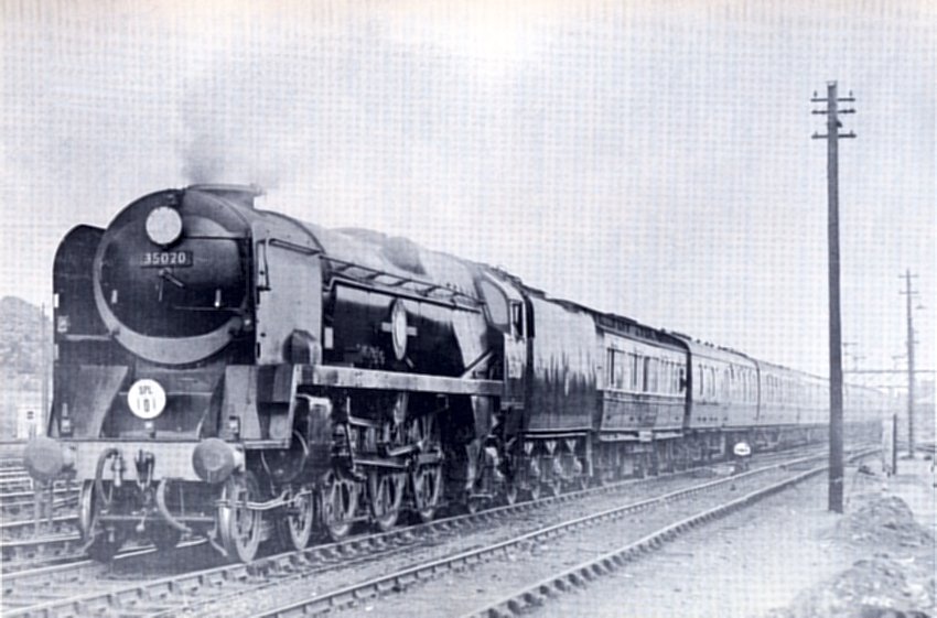
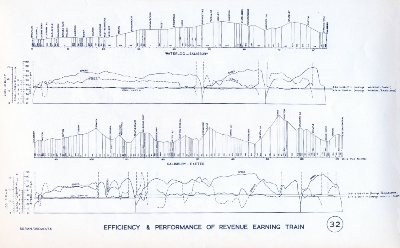
The Controlled Road Tests were made on the Salisbury - Exeter route of the Southern Region in both directions. A gradient section of this route is shown as part of Graph 32 below.
To follow the Controlled Road Tests, it was arranged for the locomotive to work certain representative service trains between Waterloo and Exeter. The western section of this route was that over which the Controlled Road Tests were made. The graph below shows the gradient section of the whole route.
The same coal was used for the service trains and the purpose of using the dynamometer car in the trains was for observational purposes only. In other directions too there was no interference with normal practice and procedure. All water used was measured and every pound of coal accounted for including that used for steam raising.
It was considered that the distinctive natures of the eastern and western parts of the route would provide most informative evidence of the influence of the rate of working on traction efficiency and coal consumption. It was indeed hoped that the data emerging could be satisfactorily reconciled with the results of the Controlled Road Tests and thus provide locomotive engineers with an answer to a question and a solution to a problem which have exercised them since the early days of locomotion.
The "Merchant Navy" Class had long enjoyed a reputation for high performance under adverse traffic conditions and it was thought that some quantifiable evidence would be gathered on this subject during the course of the trials, especially as the western part was particularly conducive to high performance.
The Bulletin, in its latter part, showed what success attended the first of these aspirations. As to the second, the accident of contingencies provided what ranked amongst the best performances of the ":Merchant Navy" locomotive.
Mechanical troubles were absent. The valve gear proved to be as flexible as any normal arrangement. The locomotive steamed freely on the Controlled Road Tests, amongst hundreds of samples of smokebox gas taken, all were apparently free of carbon monoxide, which indeed could be produced only when access of air to the ashpan was intentionally restricted. The same general remarks apply also to the observed service trains where it appeared temporarily only when the fireman was building up the firebed in anticipation of the driver requiring a period of high power output.
The tests were carried out and the Bulletin was prepared by the C.M.& E.E. Department of the Western Region in conjunction with the C.M.& E.E. Department of the Southern Region and under the auspices of the Locomotive Testing Joint Sub-Committee.
Here are a few pictures of the tests and a summary graph.