Brian King
Unknown
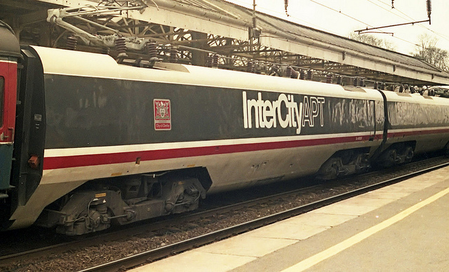
APT-P high speed pantograph testing on WCML in 1979
|
Before I became involved with the replacement of the APT-P two-stage pantograph with the BR/BW Highspeed pan in 1982 , my colleagues in the APT-P Group of the DM&EE had developed a better performing version of the existing Faiveley AMBR standard pantograph by adding an additional secondary suspension of a mini-diamond-frame pan at the apex. From 1977, once the Dynamics Section became involved as part of the high speed current collection programme, pantographs were no longer viewed as electrical equipment but as a mechanical device which happened to carry current and the BR/BW highspeed pan was fitted to the APT-P with very encouraging results when tested on Sc R. A series of tests was carried out in December 1979 on the Scottish Region to evaluate the performance of the prototype Advanced Passenger Train with its original two-stage pantograph at speeds between 210km/h and 260km/h. Part of the test programme included a performance assessment of the two-stage pantograph and its interaction with the overhead equipment, for which measurements were made both on board the train and at the trackside. The objective of running the APT at its design maximum of 255km/h was achieved, but it is clear that the standard overhead line equipment and pantograph are unsatisfactory for these high speeds in their present form. The major problem with the pantograph was the large aerodynamic force generated by the main frame at high speeds, which compressed the secondary suspension and applied large forces to the overhead line, thus giving high uplift with consequent risk of damage. Whilst these problems were due to high train speed and moderate head winds, it is likely that a train in service running at say 210km/h with a 50km/h head wind would be generating similar levels of force. It therefore seems essential to modify the pantograph before regular service begins. The modification of the standard MkIII overhead equipment, by introducing stitches, was very successful and achieved a substantial reduction of both arcing and force variation. Assuming the pantograph mean uplift force was reduced, this would probably have been suitable for high speed operation. Two incidents where the pantograph struck the fixed equipment while running on the stitched overhead line would not have occurred had the pantograph uplift force been lower, and it was felt they were not attributed to the stitched equipment. They did however demonstrate how robust the pantograph was. |
Click on the picture for a bigger image - photos are BR official unless otherwise indicated
|
|
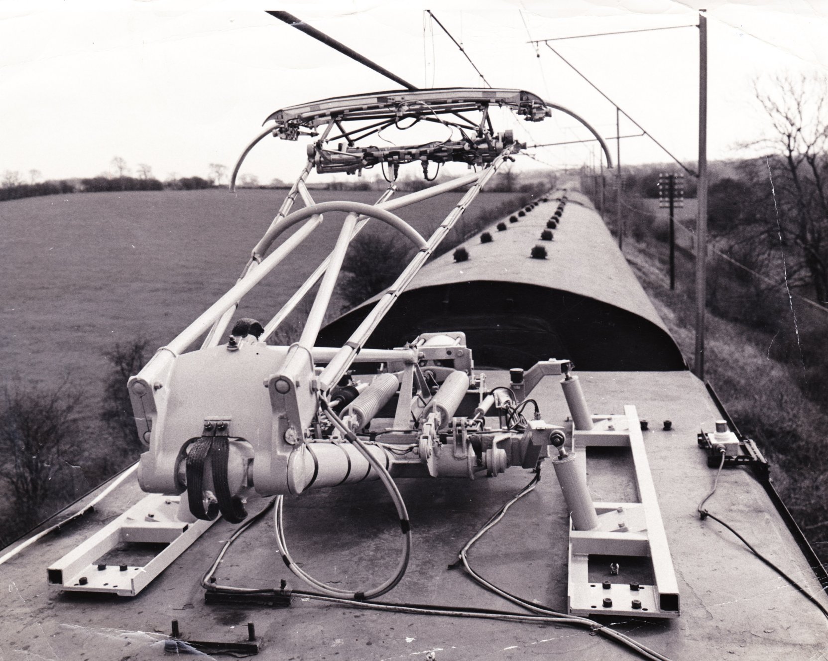
The APT-P 2-stage pantograph on test at Old Dalby |
|
|
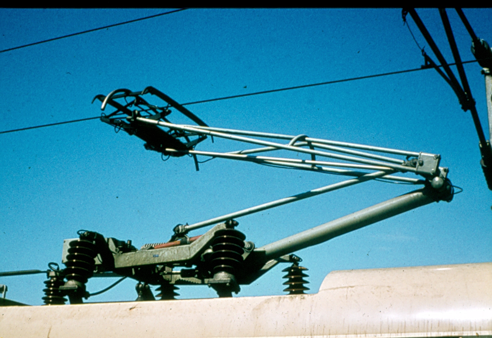
The APT-P 2-stage
pantograph Brian King |
|
|
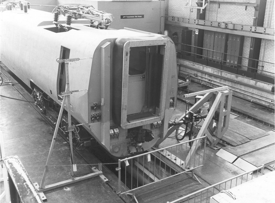
APT-P pantograph in the Vehicles Lab at RTC c1977 |
|
|
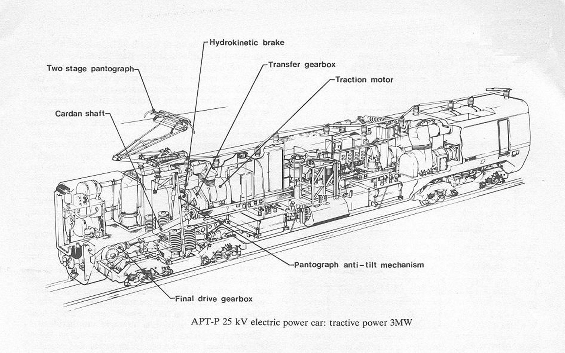
Isometric drawing of the power car showing the original pantograph |
|
|
APT-P power car
fitted with the original pantograph at Oxenholme.c1978 Unknown |