![]()
P R Howe
|
The trials described in this Bulletin were carried out by the Dynamometer Car Section, Chief Mechanical & Electrical Engineer’s Department, Eastern Region, on one of the initial batch of 1250 B.H.P. Type 2 diesel-electric locomotives built within the Brush Group and erected by Brush Traction Limited at Loughborough. These locomotives were designed for mixed traffic working and are fitted with a train heating boiler so that they are suitable for working passenger trains. The trials which were carried out on the Eastern Region of British Railways took place in November and December 1958 on behalf of the Locomotive Testing Joint Sub-Committee and the results are set out as a record of the performance of one of the prototype locomotives of the Modernisation Scheme. OBJECTS OF THE TRIALS The objects of the trials were to establish the performance and efficiency characteristics of the locomotive and to relate these results to the actual performance on service trains with respect to the capabilities of the locomotive for different types of duty and the assessment of load and time schedules. SCOPE OF THE TRIALS In order to attain the objects of the trials it was decided to control some of the tests, to obtain working at constant fuel rates so that the performance over the whole working range could be explored. This necessitated the use of special trains but the results obtained from these tests were related to the performance of the locomotive on normal service passenger and freight services. . On these test trains much of the working was in the high speed range and to extend this to low speeds, tests were made on special freight trains with heavy loads. THE LOCOMOTIVE AND EQUIPMENT The Brush Traction 1250 B.H.P. A.l.A. A.l.A. Type 2 diesel-electric locomotive was designed for working moderate speed passenger and freight services. The total weight of the locomotive is 104 tons with a continuous rating of 22600 lb. at 16.5 m.p.h., equivalent to about 14% of the adhesive weight of 72 tons. The locomotive is powered by a Mirlees, Vee-type 12 cylinder, turbo-charged four-stroke Diesel engine with a rating of 1250 b.h.p. at 850 r.p.m. under normal temperature and altitude conditions. The engine is fitted with a Woodward governor in which is incorporated a device to automatically shut down the engine when the oil pressure falls below a certain level. When the engine speed exceeds a given limit, a separate overspeed device over-rides the main engine governor and moves the fuel pumps over to the 'No Fuel' position. METHOD OF CONDUCTING TRIALS Locomotive No. D55l6 was used for the trials which were all carried out on the Great Eastern Section of the Eastern Region on routes normal worked by this type of locomotive. At the completion of the trials the locomotive had a mileage of 16,700 miles and had only received normal servicing apart from fitting with a new type of scraper ring. . Prior to the commencement of the trials the locomotive was given a test run so that an engineer, representing Brush Traction Limited, could check that all equipment was working satisfactorily. The locomotive was specially fitted with test instruments for observations of both engine and transmission performances. The thermometers to measure the engine exhaust gas, cooling water, lubricating oil, fuel oil and air temperatures were thermocouple and resistance elements with remote reading indicators mounted on an instrument panel in the dynamometer car. Lubricating oil, fuel oil and turbo-charger boost pressures were observed in the engine compartments. A positive displacement type fuel meter was fitted into the fuel supply line immediately before the main fuel rail and provision was made to bye-pass surplus fuel back into a closed circuit. The meter was fitted with electric contacts so that a continuous record could be made of the fuel consumption. Ammeters and voltmeters were installed in both the main and auxiliary generator circuits to measure the output of the generators and these meters, together with a tachometer for engine speed, were mounted in the dynamometer car. A continuous record was made of drawbar tractive effort, time, speed, work done, distance, etc. and these were recorded on either a time or distance base as required, together with the fuel consumption. The other observations were logged at regular intervals and co-ordinated on to the dynamometer car record so that they could be identified later with a particular locomotive performance. . The fuel oil was sampled each time the tanks were refilled. The Gross Calorific Value for each sample was found to be almost the same therefore an average figure of 19800 B.Th.U/lb. has been taken as representative of the fuel used during the trials and details of a representative analysis are given in Table 2. (a) Controlled road tests with special trains The controlled road tests were carried out on the section of line between Stratford and Norwich Thorpe, via Ipswich. From the full power curve of designed rail tractive effort characteristics, Fig. 3, a suitable timing and load for the route was calculated to give 'Working conditions over the full speed range up to 80 m.p.h Similarly, the loads which would enable the same schedule to be maintained when working in notch positions 10, 9 and 8 were calculated. The test route was 110 miles long but not all of this mileage could be utilised for test purposes due to out of course checks and temporary speed restrictions. However during the test periods the controller was Ieft in the appropriate notch position for all the working and at starts the controller was moved up into the given position as quickly as possible. b) Tests on service passenger trains The same route was used for these tests as for the controlled tests except that they took place over the whole route from Liverpool Street to Norwich Thorpe. The Down train was the 8.30 a.m. with a load. of 10 vehicles, 332 tons, from Liverpool Street to Ipswich where 4 vehicles were detached and the remainder, 204 tons, worked forward to Norwich. This train had a total of seven intermediate stops. The Up train, the 2.45 p.m. from Norwich required a different type of working being one of the trains with a two hour timing from Norwich to London including a stop of 2 minutes at Ipswich. With a load of 7 vehicles 238 tons, this train required much faster running at full power. Similar data on the performance was obtained as on the controlled tests except that these tests were purely observational and no control 'as exercised on the working. c) Tests on service freight trains Similar observational tests were carried out on normal freight train workings between Temple Mills and Whitemoor. The Down train was the 1.37 p.m. from Temple Mills, a class 'E' Unbraked goods with a load of 55 empty wagons. The Up train was a Class 'E' Braked goods, 8.36 a. m. from Whitemoor with a load of mixed traffic equal to 39 loaded wagons. It was unfortunate that, from a testing point of view, these trains were subject to some delay due to bad weather conditions. d) Special freight workings In order to obtain information on maximum starting efforts, tests were carried out on heavily loaded trains in the sidings at Whitemoor and on trains with loads of 900, 1000 and 1100 tons on the rising grades between Cambridge and Elsenham. The latter tests also provided the opportunity for observing the full power performance at lower speeds than had been possible with the other type of working. Here are a few pictures of the tests and a summary graph. |
Pictures are BR official except where credited
|
|
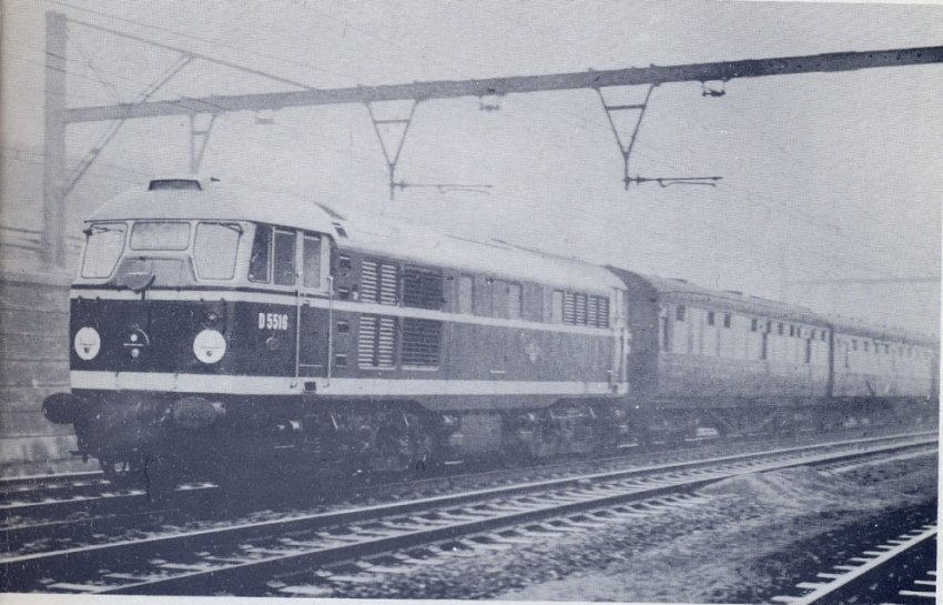
D5516 on test hauling the 08.30 Liverpool Street to Norwich service up Brentwood Bank |
|
BR diagram book entry for the Brush Type 2 loco |
|
|
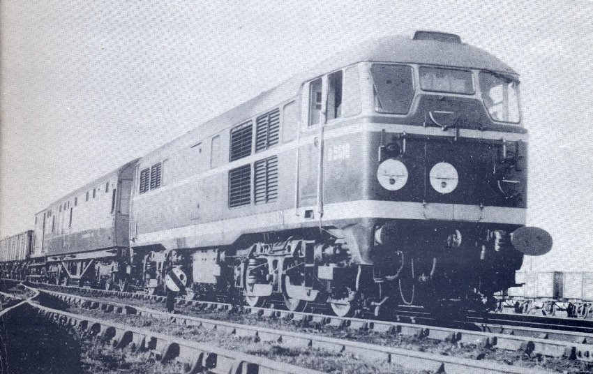
D5516 leaving Whitemoor Yard
with ex- ER No:2 Dynamometer car and a fitted freight train. P R Howe |
|
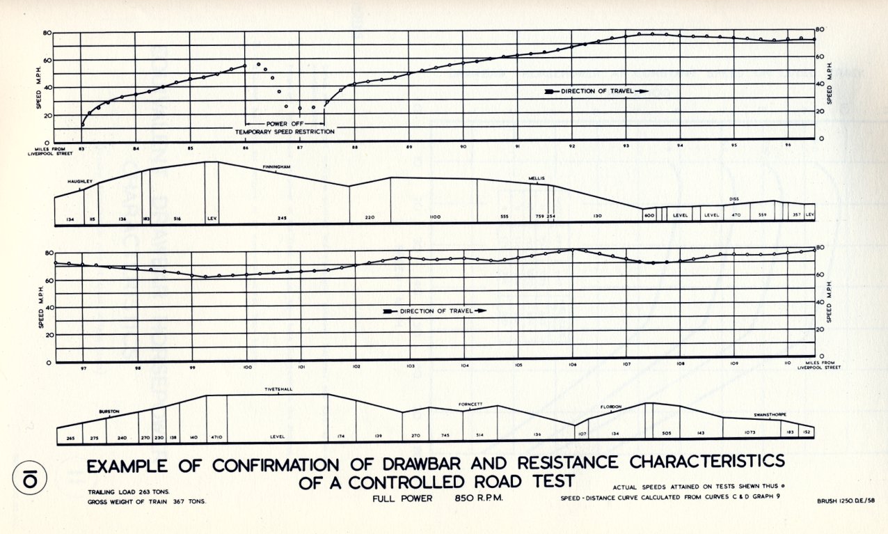
Controlled road test results under full power |
|
|
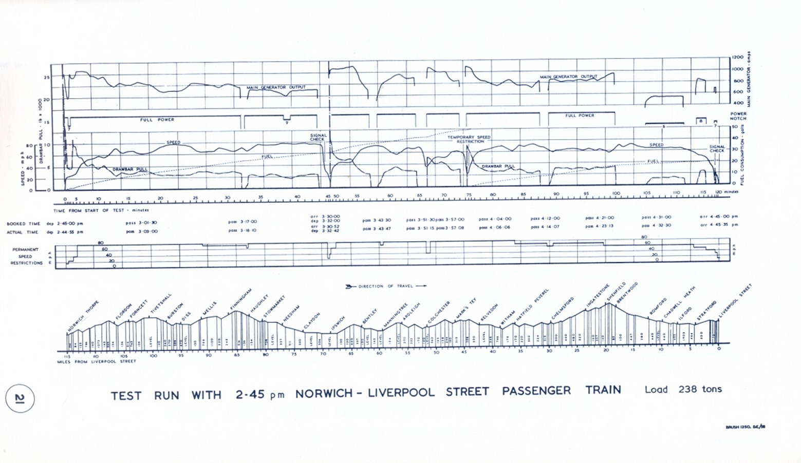
Passenger train results for Norwich to Liverpool Street | ||